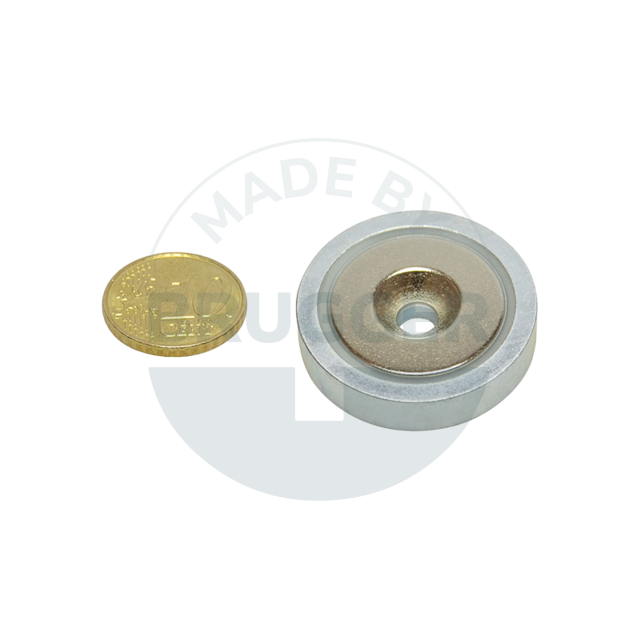
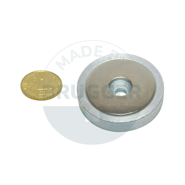
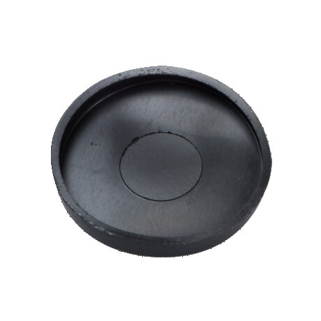
Flat pot magnets of Neodymium-iron-boron (NdFeB)

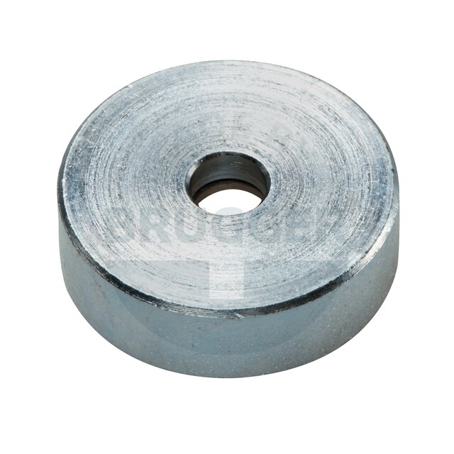
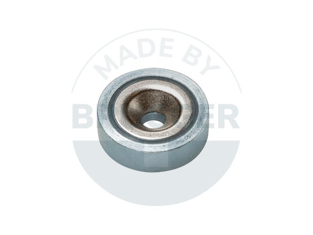
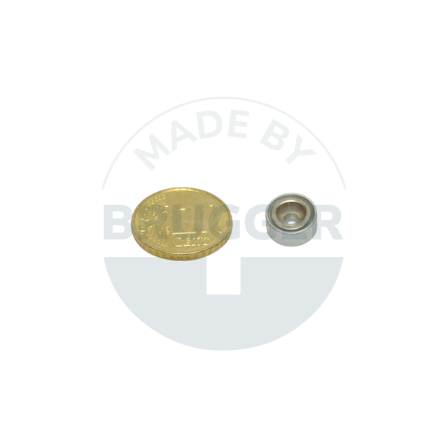
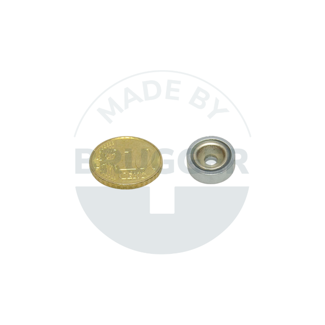
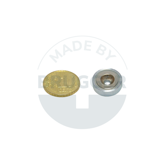
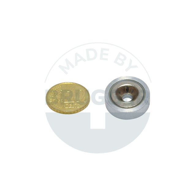
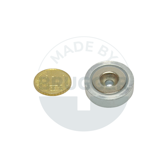
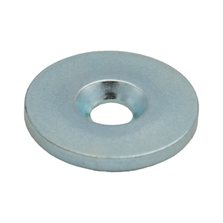
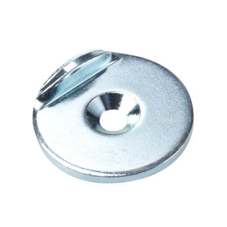
Pot magnets made of NdFeB, steel housing, with hole and countersink, galvanised

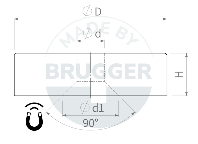
technical drawing Pot magnets made of NdFeB with hole and countersink, galvanised | © Brugger GmbH
Pot magnet of NdFeB steel housing with bore and countersink galvanised 20mm | © Brugger GmbH
technical drawing Pot magnets made of NdFeB with hole and countersink, galvanised | © Brugger GmbH
Pot magnet of NdFeB steel housing with bore and countersink galvanised 20mm | © Brugger GmbH
technical drawing Pot magnets made of NdFeB with hole and countersink, galvanised | © Brugger GmbH

PRODUCT INFORMATION:
Pot magnets use a galvanised metal pot to maximise their adhesive force. The magnetic core is located inside the pot, leaving the holding surface free. By redirecting the magnetic flux through the pot, the force is significantly increased. This enables even small magnets to develop a surprising holding force. The versatile uses of pot magnets range from industrial applications, where they serve as gripper magnets for transporting metal parts (in this variant with bore and countersink), to numerous other applications.

As an alternative to the standard version, we also offer customised solutions:
" Black galvanised surface for housing, resulting in higher corrosion resistance (up to 720 hours in a salt spray test - depending on the magnet material)

Data sheet
Product variants
Article numberD mmd mmd1 mmH mmAdhesive force* NWeight gTemperature °C
F10-NdCv10 +0.1/-0.12,6 +0.1/-0.15,2 +1/04,5 +0.1/-0.119280 Download CAD file
F13-NdCv13 +0.1/-0.13,5 +0.1/-0.16,6 +1/04,5 +0.1/-0.140480 Download CAD file
F16-NdCv16 +0.1/-0.13,5 +0.1/-0.16,6 +1/04,5 +0.1/-0.175680 Download CAD file
F20-NdCv20 +0.1/-0.14,5 +0.1/-0.19,3 +1/06 +0.1/-0.11051380 Download CAD file
F25-NdCv25 +0.1/-0.14,5 +0.1/-0.19 +1/07 +0.2/-0.21602480 Download CAD file
F32-NdCv32 +0.1/-0.15,5 +0.1/-0.111 +1/07 +0.2/-0.23103980 Download CAD file
F40-NdCv40 +0.1/-0.15,5 +0.1/-0.110,3 +1/08 +0.2/-0.25707380 Download CAD file
The housings are manufactured with high precision from bar material by turning and machining. This type of production is partially reflected in the appearance (so-called turning grooves). However, these are only visible and are barely noticeable due to the low roughness.
* The forces have been determined at room temperature on a polished plate made of steel (S235JR according to DIN 10 025) with a thickness of 10 mm (1kg~10N). A deviation of up to -10% from the specified value is possible in exceptional cases. In general, the value is exceeded. The type of application (installation situation, temperatures, counter anchors, etc.) sometimes influence the forces enormously. The values given are for orientation purposes. Let our experts advise you.